


Helpers Lab USB Power Meter USB 3.1 Tester Digital Multimeter Current Tester Voltage Detector Lua Interpreter Integrated DC 26V 6A PD 2.0/3.0 QC 2.0/3.0/4.0 PPS Trigger
- 0-26V 0-6A voltage & current measurement. 128*160 1.77’TFT. 4.5 digits reading for voltage and current. 0.1% maximum gain error for both voltage and current. Capacity/Energy accumulator. PD(with PPS), QC2.0, QC3.0, QC4.0, Huawei SCP, SSCP, FCP, Samsung AFC, VOOC, Super VOOC 65W trigger for charger testing.
- 【Powerful PC software】Data logging up to 1000sps. Lua program downloader. VBUS ripple viewer(3.2Msps). PD listener for device diagnosis. Fast-charge trigger and external load module can also be accessed. All functionalities can be activated simultaneously for advanced test requirements.
- 【Lua Programmable】Lua interpreter integrated, provided with various APIs, detailed documentations (Look up at point 1). Make access to almost all hardware with your own program. Scripts can be set to run on boot. Internal 12Mbytes memory can be used to store scripts, and can be used as output storage of scripts (Standard file operation supported).
- 【Quick-charge trigger class】QC 2.0, QC 3.0 trigger;Huawei FCP, SCP, SSCP trigger and SCP/SSCP smooth regulating ;Samsung AFC trigger ;VOOC (DASH/WARP) four-generation trigger and smooth regulating ;SuperVOOC trigger;The above protocols can be automatically detected ; PD2.0, 3.0 (including PPS/QC 4.0) trigger
- 【Miscellaneous functions】D+ D- voltage measurement;On-board temperature measurement ;Information reading of Apple charger
- 【Wire identification class 】E-mark cable read ; Mfi Cable read ; Apple Adapter read
Wide functionality:
0-26V 0-6A voltage & current measurement.
4.5 digits reading for voltage and current.
0.1% maximum gain error for both voltage and current.
Capacity/Energy accumulator.
PD(with PPS), QC2.0, QC3.0, QC4.0, Huawei SCP, SSCP, FCP, Samsung AFC, VOOC, Super VOOC 65W trigger for charger testing.
Type-C to Type-C, Type-A to Type-C cable resistance tester.
E-mark reader.
VOOC/Dash cable dumper.
Apple charger S/N reader.
Fast-charge protocol auto-detect mode.
Offline data (Voltage, current, D+, and D-) logging up to 100sps.
Internal 12Mbytes storage for data logging and user programs.
Power source ripple meter with 3.2Msps sample rate.
USB3.1 SuperSpeed pass-through for Type-C ports.
USB2.0 + speicial fast charge communication line (For SuperVOOC, VOOC, Dash, Warp) pass-through for Type-A ports.
128*160 1.77’ TFT. Integrated gravity sensor and buzzer for better user experience.
Powerful PC software:
Data logging up to 1000sps.
Lua program downloader.
VBUS ripple viewer(3.2Msps).
PD listener for device diagnosis.
Fast-charge trigger and external load module can also be accessed.
All functionalities can be activated simultaneously for advanced test requirements.
Lua Programmable:
Lua interpreter integrated, provided with various APIs, detailed documentations (Look up at point 1).
Make access to almost all hardware with your own program. Scripts can be set to run on boot.
Internal 12Mbytes memory can be used to store scripts, and can be used as output storage of scripts (Standard file operation supported).
Meter UI Manual
V1.00.00
Welcome to use my product 「Helpers Lab USB Multimeter」, this manual will introduce to you usages and tips of the Meter UI of the product. Please read the manual carefully and save it for the future look-up.
0.0 Warning
1 After fast-charge trigger, do not plug in any device which cannot cope with the triggered high voltage into any port.
2 While the meter monitoring Voltage & Current between one input port and one output port, do not plug-in the third device into other ports.
3 After using PD trigger or listener feature, please turn off the switch on the bottom-right side of the meter.
4 The author is not responsible for any faulty operation.
0.1 Version & Update
Due to the complexity of the features, both the firmware and the hardware can vary frequently, this manual might not be applicable for the latest firmware/hardware release.
0.2 Revision History
Nothing so far.
0.3 Structure
0.4 Current Direction
The meter can detect bi-directional current between USB-A male and female ports.
The meter can detect bi-directional current between USB-C input and USB-C output ports.
The meter can detect bi-directional current between USB-C input port and USB-A female port.
But the meter cannot detect the current between USB-C output port and USB-A female port.
0.5 General Operation Logic
In all the menus, a click on the middle key is considered as confirm, a double-click on the middle key is considered as exit, left/right click is considered as selection or adjustment. This will not be repeated in the rest of the manual.
1.0 Home
Home consists of 5 different pages, click the middle key to switch among them, their contents are described as following:
1.0.1
1st Page:
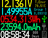
On the left side, from top to bottom are: current voltage, current, accumulated energy of the current accumulation group, accumulated capacity of the current accumulation group, accumulated time of the current accumulation group.
On the right side, from top to bottom are: board temperature, accumulation group number, equivalent resistance of the load.
On the bottom-right side, 3 icons from top to bottom represent: connection status of the PC port, connection status of modules, execution status of the lua script.
1.0.2
2nd Page:
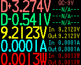
On the left side, from top to bottom, in big fonts are: D+ voltage, D- voltage, bus voltage, bus current, bus power. On the top-right side: Fast-charge protocols which are possibly running at the present.
Due to the self-power-consumption and a little bit of resistance from the measurement point to the input/output ports, there is a difference in voltage & current between actual input/output ports and the measurement point. The actual voltage, current and power are calculated and displayed in the right-bottom side of the page.
1.0.4
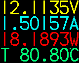
4st Page:
This page displays voltage, current, power and temperature in big fonts.
5st Page:
This page makes the meter into low-power mode. The backlight is off and only energy & capacity accumulation work is running, this is designed to improve the accumulation accuracy when no independent power supply is applied, the typical power consumption of the meter is 0.4mA @ 5V in this page.
2.0 Menus
Due to the complexity of the features, 4 different menus can be entered on home pages by doing the following:
- ‘Settings’ menu, long press the middle key to enter.
- ‘Left-Short’ menu, click the left key to enter. It includes fast-charge trigger, protocol enumeration, e-mark cable reading, cable resistance test, etc.
- ‘Left-Long’ menu, long press the left key to enter. It contains lua scripts, offline data logging, USB storage mounting, etc.
- ‘Right-Short’ menu, click the right key to enter. It contains features related to extended modules.
2.1 Settings Menu
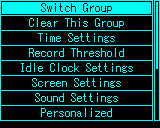
2.1.1 Settings Menu>Switch Group
The meter support 5 different accumulation groups, it is useful when you want to test different devices alternatively. You can switch between groups with this option.
2.1.2 Settings Menu>Clear This Group
Clear current accumulation group.
2.1.3 Settings Menu>Time Settings
The meter contains an RTC clock. This option is used to set the time. The time set by this option is also used for filesystem time stamp and lua scripts.
2.1.4 Settings Menu>Record Threshold
This option sets the accumulation threshold of the accumulation groups. When the current is more than this value, accumulation is running, while accumulation is paused when the current is less than this value. The range of this option is 0-200mA, when this value is set to 0, the accumulation always runs no matter how much the current is.
2.1.5 Settings Menu>Idle Clock Settings
When no user inputs and no accumulation running for a certain amount of time, the meter enters idle clock mode.
Enable/Disable Idle Clock
Enable/Disable idle clock mode.
Idle Time
Specify how much time without operation it takes to enter idle clock mode.
2.1.6 Settings Menu>Screen Settings
Enable/Disable Screen Idle
Enable or disable the screen idle behavior(The screen brightness is reduced).
Screen Idle Time
Specify how much time it takes to enter low brightness idle mode.
Brightness Settings
Set the brightness of the screen during normal operation.
Idle Brightness
Set the brightness when the screen is in low brightness idle mode.
HomePage Update Rate
Set the update speed of the homepage readings. When the speed is reduced, the accuracy is relatively better, vice versa.
Use Fahrenheit/Centigrade
Set the unit in temperature display.
Enable/Disable Equal-Resis
Set if the fourth line of the fourth page of home displays the equivalent resistance(It is the board temperature by default).
Display Direction
The meter contains an accelerometer which detects the viewing direction, this feature can be disabled.
Enable/Disable Auto-Rotation
Enable or disable auto-rotation feature.
Default Direction
This specifies the direction of the display when autorotation is disabled.
2.1.7 Settings Menu>Sound Settings
The meter contains a buzzer to provide better user experience.
Enable/Disable Touch-Tone
Enable/Disable touch-tone.
Enable/Disable Hint Sound
Enable/Disable hint sound.
Enable/Disable Warning Sound
Enable/Disable warning sound.
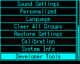
2.1.8 Settings Menu>Personalized
Theme Color
Set the theme color of meter UI.
2.1.9 Settings Menu>Language
Set the language.
2.1.10 Settings Menu>Clear All Groups
Clear all accumulation groups.
2.1.11 Settings Menu>Restore Settings
Restore settings into default.
2.1.12 Settings Menu>Calibration
Don’t enter this option.
2.1.13 Settings Menu>System Info
See system information.
2.1.14 Settings Menu>Developer Tools
Don’t enter this option.
2.2 ‘Left Short’ Menu
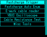
Left-click on the home page to enter ‘Left Short’ Menu.
2.2.1 Fast-Charge Trigger
The meter supports fast-charge trigger for various protocols: QC2.0/QC3.0, PD, Huawei FCP/SCP,(Super)VOOC/DASH CV Mode, Samsung AFC.
Warning
After entering the fast-charge trigger menu, all operations should be considered carefully, in short, do not plug any other device except the charger (unless you know what you are doing). The author is not responsible for any faulty operation.
QC2.0
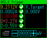
In QC2.0 mode, the user adjusts the voltage being triggered by scrolling the key to left or right. On the left side, current meter readings are displayed to check if a trigger is successful.
Double-click the middle key to go back to home-page, the triggered voltage maintains.
QC3.0
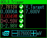
In QC3.0 mode, the user adjusts the voltage being triggered by scrolling the key to left or right (200mV per step as the protocol defined.).
Double-click the middle key to go back to home-page, the triggered voltage maintains.
Power Delivery 2.0/3.0
The meter supports requesting specified voltage from a charger running PD protocol. The internal PD transceiver is separated to the outside with a switch, which can be found on the right-bottom side of the meter.
To allow PD transceiver to communicate with the charger, turn the switch on the right-bottom side of the meter into “ON” position. After using this feature, you should turn it back into “OFF” position.
Connect the meter and the charger with a Type-C to Type-C cable, if nothing goes wrong, the meter should start up. Enter fast-charge trigger menu, select “Power Delivery”, the meter might reset, after that, the meter reports the voltage & current that the charger supports.
You can also press and hold the middle button while start-up to enter PD trigger mode, it’s a shortcut for batch tests.
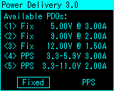
A charger’s report is shown above.
This charger is PD3.0 and PPS capable. It has 3 fixed PDOs and 2 PPS PDOs. Scroll to select the type of PDO you want to trigger(fixed or PPS).
Note that not every PD charger supports PPS, it’s highly possible that you will have only one choice “Fixed” here.
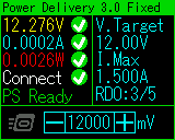
In fixed mode, the user adjust the voltage being triggered by scrolling the key to left or right.
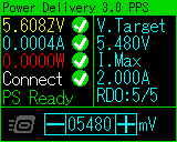
In PPS mode, the user adjusts the voltage being triggered by scrolling the key to left or right (Each step is 20mV defined by protocol).
Double-click the middle key to go back to home-page, the triggered voltage maintains.
Huawei FCP
The same as QC2.0 mode except the protocol is different.
Samsung AFC
The same as QC2.0 mode except the protocol is different.
Huawei SCP
The same as QC3.0 mode except the protocol is different.
Huawei SSCP
The same as QC3.0 mode except the protocol is different.
VOOC/DASH/WARP CV
The same as QC3.0 mode except the protocol is different.
Super VOOC
Notice that Super VOOC need a load more than 500mA to be triggered properly, and Super VOOC has only one step of voltage which is 10.5V.
2.2.1 Fast-Charge Release
After triggering any fast-charge protocol, if you want to discard the voltage triggered, enter ‘Left Short’ menu again and select fast-charge release.
2.2.2 Fast-Charge Auto Enum
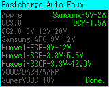
In “Fast-Charge Auto Enum” mode, the meter tries to trigger fast-charge protocols one by one, and list them on the screen, if one protocol is supported, it is displayed green, otherwise it is displayed in gray.
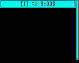
2.2.3 E-mark Cable Reader
This dumps the data of the E-mark chip(If present) inside C-C cable.
Power the meter with USB-A port or PC port (More recommended to power with PC port), switch the PD communication switch on the right-bottom side of the meter into “ON” position. Enter this mode, then plug-in the cable being tested (The other side of the cable should be leave float).
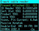
The top of the screen shows the CC pin which is in communication with the cable, followed by the raw data received from the cable.
Below the raw data is the analysis of the cable, providing information like cable type, brand, HW/FW version, etc.
The data is refreshed every 1 second, hot-plug is supported. Double-click the middle key to exit the mode. Please don’t forget to switch the PD communication switch back into “OFF” position.
2.2.4 VBUS Oscilloscope
The meter contains an ADC and related circuit to display the AC coupled voltage on VBUS.
The maximum sample rate is 3.2Msps, with bandwidth 1.6MHZ, it’s applicable for viewing ripple of most chargers, but the ripple of some power-banks might not be shown properly as they usually come with a higher frequency.
Read the ripple frequency on the top-right ride, Vpp on the bottom-right side.
Scroll the key to left & right to adjust the sample frequency, click the middle key to pause or continue.
2.2.5 Cable Resistance Test
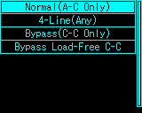
2.2.5.1 Cable Resistance Test>Normal(A-C Only)
Normal mode calculates the cable resistance by comparing the voltage drop with and without the cable on the same load current.
The first step is: Plug in a power source to the USB-A male port, and plug-in a constant-current load to the USB-A female port, click the middle key to confirm.
Then unplug the meter from the power source.
Reconnect the meter to the power source with the A-C cable being tested.
And plug-in the same load as before, click the middle key to confirm.
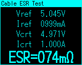
Then you should be able to read out the resistance.
2.2.5.2 Cable Resistance Test>4-Line(Any)
The meter provides the software implementation of this method only, for detailed information, contact your accessory provider.
2.2.5.3 Cable Resistance Test>Bypass(C-C Only)
This method is capable of calculating the resistance of the positive bus wire inside the C-C cable, and therefore estimate the full cable resistance. Usually, the positive and the negative wire inside the cable share the same diameter and material, so the result is usually reliable.
The first step is: Plug in a power source to the USB-A male port, and plug-in a constant-current load to the USB-A female port, click the middle key to confirm.
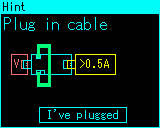
Then you plug-in your C-C cable being tested to both Type-C ports of the meter, click the middle key to confirm.
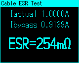
Then you should be able to read out the resistance.
You can replace the being tested cable more than once to do a batch test.
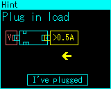
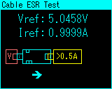
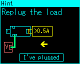
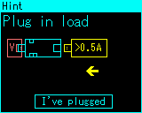
2.2.5.4 Cable Resistance Test>Bypass Load-Free C-C
This shares the same principle as 2.25.3, the difference is, the meter utilizes its internal small resistor load to replace the external load to provide more convenience.
You should connect a 5V power source to the USB-A male port of the meter, enter this method:
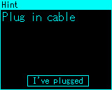
Then you plug-in your C-C cable being tested to both Type-C ports of the meter, click the middle key to confirm.
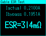
Then you should be able to read out the resistance.
You can replace the being tested cable more than once to do a batch test.
2.2.6 Misc Tools
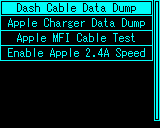
2.2.6.1 Dash Cable Data Dump
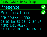
This is able to check the validity of a DASH/VOOC/WARP cable.
Power up the meter with PC port.
Plug in USB-A connector of the DASH/VOOC/WARP cable into the USB-A female port of the meter.
The program reads out the content inside the cable.
It refreshes automatically, you can exit by double-clicking the middle key.
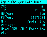
2.2.6.2 Apple Charger Data Dump
This is able to dump information saved inside an apple PD charger.
Connect the charger and the meter with a C-C cable (You also need to turn on the PD communication switch).
Select this option, wait a few seconds, the meter should show the data of the charger:
2.2.6.3 Apple MFI Cable Test
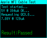
Connect the meter to a QC3.0 supported charger, then connect the MFI cable to the output port of the meter, the other side of the MFI cable should be left float.
Enter this option, wait a few seconds for the result.
Also notice the validity of this method is no longer proved.
2.2.6.4 Apple 2.4A
This will apply recognition voltage on D+ & D- lines to make the apple device convinced that it’s connected to an apple charger, therefore increase the charging speed.
2.3 ‘Left Long’ Menu
Long-press the left key to enter “Left Long” menu.
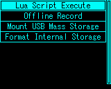
2.3.1 Lua Script Execute/Stop
Select a script from internal storage 0:/lua/user to run.
For details of lua scripts, please visit: Lua Programming Overview
2.3.2 Offline Record
The meter is able to log voltage & current into the internal storage, after data logging, you can open them in PC software.
The offline record files are saved in “0:/record/”.
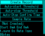
2.3.2.1 Create/Stop Record
Create or stop the record manually.
2.3.2.2 Auto-start Threshold
Specify the start threshold current after the record created, if 0mA is given, the record will start immediately after creating.
2.3.2.3 Auto-stop Threshold
Specify the stop threshold current under which the record will be stopped. If 0mA is given, the record will never stop automatically.
2.3.2.4 Auto-stop Confirm Time
Specify the time for the auto-stop condition to be triggered. If the device consumes less than the auto-stop threshold for this amount of time, auto-stop will be triggered.
2.3.2.5 Sample Rate
Set the sample rate of the offline record. Higher sample rates record more details, also consume more space.
This can be set in the range of 1-100sps.
2.3.3 Mount/Umount USB Mass Storage
This mount/umount the internal storage to the PC as a mass storage device.

The user can access internal storage, read offline record, copy in lua scripts, copy in firmware package to upgrade, etc.
2.3.4 Format Internal Storage
Format the internal storage.
2.4 “Right Click” Menu
Right click on the home page to enter “Right Click” menu.
The user utilize and manage the modules in this menu.
So far, there’s only one module “SM-LD-01” is available.
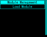
2.4.1 Module Management
Select target module:
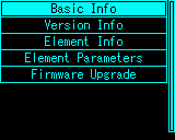
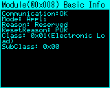
2.4.1.1 Basic Info
Show basic information of the module.
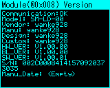
2.4.1.2 Version Info
Show version information of the module.
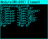
2.4.1.3 Element info
List elements inside the module.
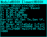
2.4.1.4 Element Parameters
Show parameters of a specified element.
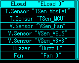
Select an element to view its parameters:
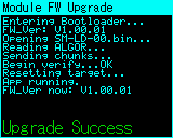
2.4.1.5 Firmware Upgrade
You can perform a firmware upgrade to the module.
The upgrade package will be released on the [website] (https://yk-lab.org:666/). You should copy the package into the internal storage and perform a module firmware upgrade.
2.4.2 Load Module
The user controls load module in this option.
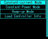
2.4.2.1 Constant-current Mode
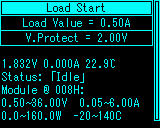
Set proper load value and protection voltage, then click “Load Start” to enable the load.
Voltage, current, status information, etc. is shown at the bottom.
2.4.2.2 Constant-power Mode

Set proper load value and protection voltage, then click “Load Start” to enable the load.
Voltage, current, status information, etc. is shown at the bottom.
2.4.2.3 Ramp-up Mode
Ramp-up mode will increase the current gradually in the specified current range.
Select Ramp-up mode, set the parameters one by one:
Start Current:The current where the ramping begins.
End Current:The current where the ramping ends.
Slope:The slope pf the ramping.
V.Protect: Set the voltage below which the test will be stopped event without completion.
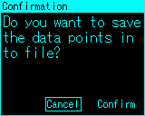
After setting the parameters, you can choose whether the voltage & current data will be logged or not.
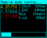
Then it enters running mode.
Wait for the progress to be done.
After completion, the meter gives you a graph of voltage & current during the ramping, double-click the middle key to exit.
If you just want to get a rough look at the voltage & current relation of your charger, you can simply not to log the data into any file. If you want to analysis them carefully, you should save the data points into a file (Select “Confirm” in the dialogue before).
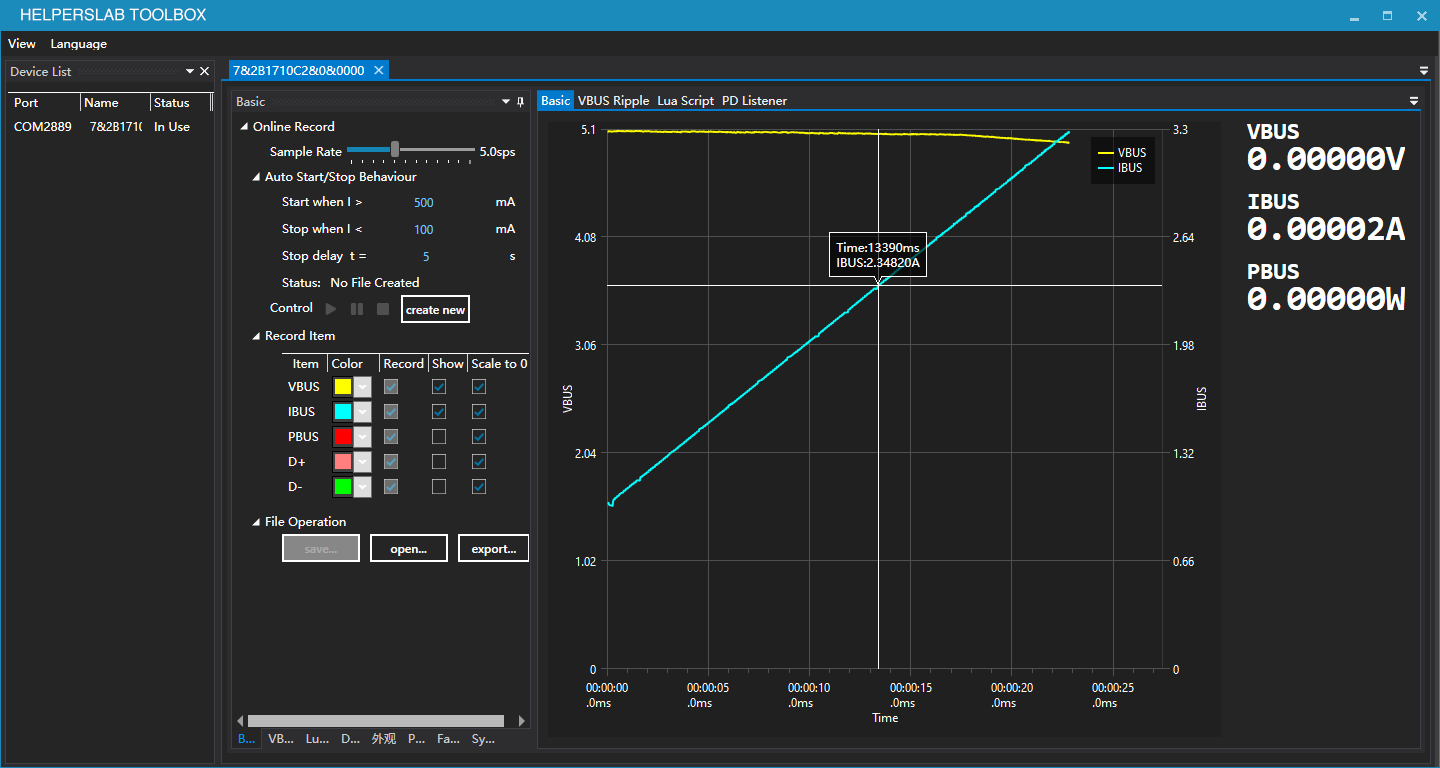
Open the ramp-up log file in the PC software to get a further look.
For detailed description of the PC software, please see PC Software Manual.
2.4.2.4 Load Controller Info
View the load controller information, for debug uses.
2.4.2.5 Load extended home page
If any load module is connected, one more page is added to the home page:
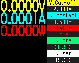
Here, most of the values should be familiar.
T.Core is the mosfet temperature of the load module.
T.User is the reading of the user plugged temperature sensor, it is usually attached to the being tested device. For details of this accessory, please see: TODO TODO.
3.0 Misc
3.1 About USB3.1
Here USB3.1 refers to USB3.1 Gen1 & Gen2.
The meter partially supports USB3.1 super-speed signaling, this is not advertised, it’s not guaranteed to pass all USB3.1 signal normally.
This is due to extra PCB routing of the meter for USB3.1 signal, the signal is attenuated making poor compatibility. If you want to test USB3.1 devices whatsoever, please follow the tips below to make the setup work as well as possible:
1.When testing USB3.1 devices through USB-A ports, collect the shortest possible cable with good quality.
2.When testing USB3.1 devices through Type-C ports, collect the shortest possible cable with good quality. Replace at least one of the cables with a Type-C male to male plug converter, replace all of the two when necessary.
2.2 Lua Script
This article only describes lua related features on the software, for more information, please go here.
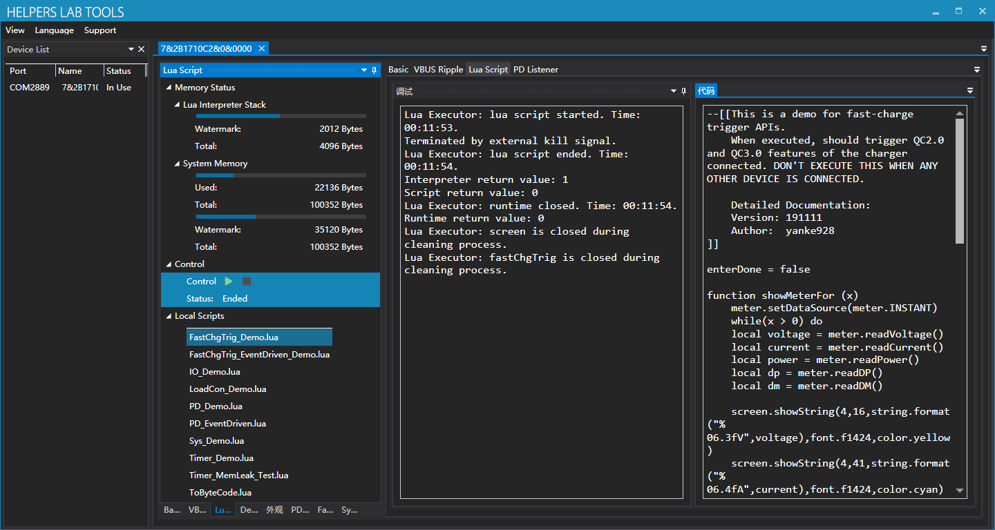
2.2.1 Memory Status
Real-time memory status is shown here.
2.2.2 Local Scripts
Here local scripts are listed, example codes are stored by default.
2.2.3 Debug
This is the output terminal. Outputs of Lua program, Lua executor, Lua Interpreter are all here.
2.2.4 Code
Currently loaded code, click green button to download and execute.
2.2 FastCharge Trigger
You can use fast-charge trigger feature on the PC software as well as the meter itself.
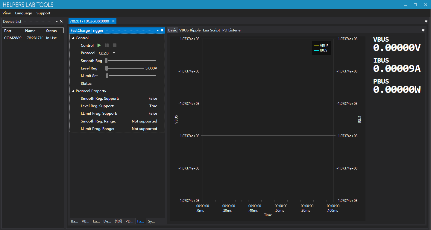
2.3.1 Select the protocol
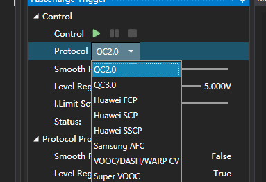
Select the protocol being triggered here.
2.3.2 Protocol Properties
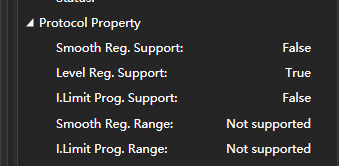
Here properties of the protocol you’ve selected are shown.
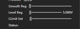
2.3.3 Adjustment
After click the green start button, you can make adjustments on voltage and current limit:
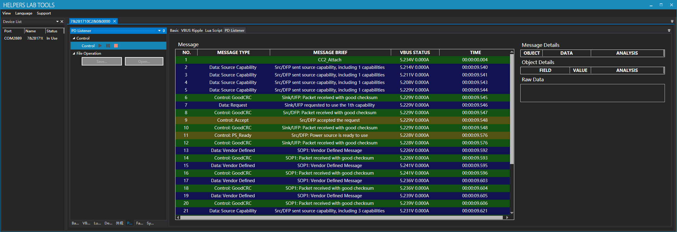
2.4 PD Listener
To use listener, please follow the following procedure strictly:
- Make sure PD communication switch is on the “ON” position.
- Connect the charger and the meter with a C-C cable.
- Click green start button.
- Use another C-C cable to connect the other Type-C port to your being tested device.
- If you expected some message to appear but it didn’t, you might need to flip one of the Type-C plug connected on the meter.
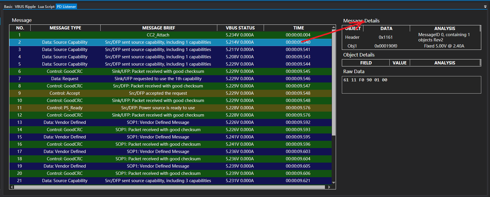
2.4.1 Message Details
Click a message and you’ll see message details on the right side:
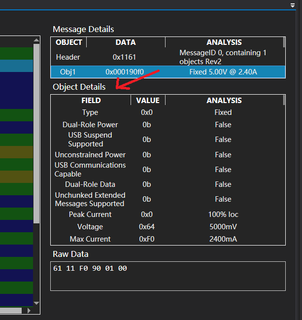
2.4.2 Object Details
Click a data object and you’ll see object details on the bottom:
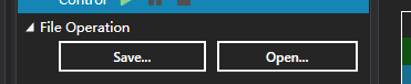
2.4.2 File Operations
You can save and open PD listener stream:
2.5 Modules
The module panel contains the expansion modules accessible from the software.
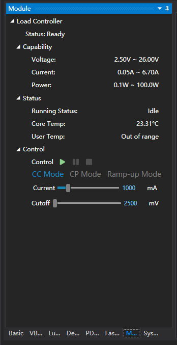
2.5.1 Load Controller
You can operate load modules mounted on the meter here.
Capabilities and the status of the module is shown above.
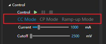
To start the load, you select the load mode here first. Modes:
CC Mode: Constant current mode, usually used for aging or capacity tests.
CP Mode: Constant power mode, usually used for aging or capacity tests.
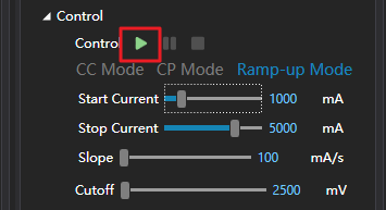
Ramp-Up Mode: In this mode, the load is increased gradually, from Start Current , to Stop Current , with specified slope Slope . This is usually used to determine the maximum load capability of a power source. Apply this combined with graphing yields a V-I graph of the power source.
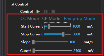
Then, you set the parameters for your mode (Different modes have different parameters). You can either drag the scrollbar or edit the value in the textbox directly.

Finally, you click the start button.
2.6 System
2.6.1 Firmware Update
Click “Update” to perform a firmware update, this process should take around 20 seconds.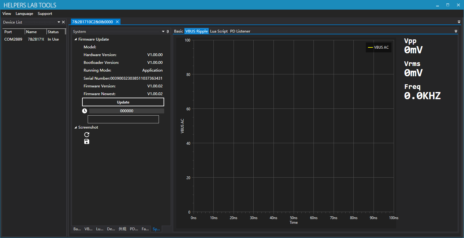
2.6.2 Screenshot
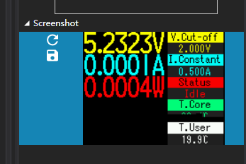
Click refresh button to capture new screenshot, click save button to save the screen shit.
Notice that some UI might not be able to be captured (Mostly graphing like VBUS oscilloscope, VBUS & IBUS graph), as they utilizes different graphic mode.


